LNER "Quad-arts"
This nickname for the articulated trains at King's Cross's is widely used by modellers and convenient - but it is confusing for two reasons:
- they served as 8-sets with two, slightly different, quadruplets permanently-coupled together and were used mainly for the Inner Suburban service. trains.
- Gresley also designed quadruplets for Liverpool Street but to a different specification and to run singly in Outer Suburban service on the line to Hertford. These I shall cover separately.
There have long been plastic kits for the King's Cross quadruplets - the all-3rd and the composite - in the Kirk range, and more recently, in etched brass from RDEB. Before describing a model from the former stable, here's an outline of the basic types.
The King's Cross "quad-arts"
There is already a separate topic describing the KX service (see link below). The design originated under Gresley in GNR days and there were three periods of construction:
1921 |
GNR |
Fox bogies |
Set Nos. 48-66 |
1923-24 |
GNR/LNER |
Gresley bogies (8' heavy) |
Set Nos. 67-76 |
1925-28 |
LNER |
Gresley bogies (8'6" heavy) |
Set Nos. 77-94 |
Individual numbers can be found in Michael Harris's final book "LNER Standard Gresley Carriages" (1998) - and in the comprehensive and voluminous notes on the Isinglass Drawings: 4/2/1-4 (substitute the precursor 4 for a 7 for O-gauge, if available).
Details - Carriages which served a long time tended to be modified. For example, GNR aspects in the first two designs concerning the opening toplights were gradually eliminated. In the final series, ventilator bonnets were fitted over the doors in the normal fashion but corrosion led to their removal. Fittings on the ends also appear to have changed although this is harder to quantity. The nature of these changes as sets passed through the works meant that there tended to be a mixture of variations running together, which I have tried to show in the following pictures.
It's often forgotten that the GN Section retained 2nd Class accommodation in London and the composite quad-arts were built with 1st, 2nd and 3rd Class compartments. The 2nd Class was abandoned in 1938 and 1st Class during the War, in 1942. Only then were all the quad-art trains entirely 3rd class. An exception was Set No 85 (see "LNER Suburban - King's Cross" topic) in which 1st Class was restored.
GNR-built sets of 1921

In a scene from 1931, N2 No 4766 is approaching Wood Green with a 1921 GNR "quad-art" train. Clearly visible is the rebated guard's end with GN-style ducket and hinged, opening toplights in the compartment windows. The doors have fixed toplights but it's a warm day and many of the main window toplights are open - it was a feature of GNR-based designs that tends to be overlooked. They were later made rigid, and then eliminated altogether. To the right, a North London Railway train is headed by LMS "Jinty" No 16594, hauling ancient NLR 4w carriages. What a contrast! Photo: Author's collection.
Click on the image for an enlargement
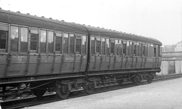
Seen in BR days on 31st August 1956, with apologies for the quality of the print, is the outer pair E48601-2E of 1921 GNR Set No 61 in which the recessed guard's end, ducket, and heavy 8ft Fox bogies are prominent. The opening toplights in the passenger windows have been removed but the glazed toplight in the doors remain. The picture was taken at Hull, presumably to help with excursions in the NE Region. Photo: H.C.Casserley 90220.
Click on the image for an enlargement
GNR/LNER hybrids of 1923-24
By a quirk of randomness, I have many pictures of trains made up with the first and last designs, but none of the hybrid designs built in between. However, there are some good detail views.
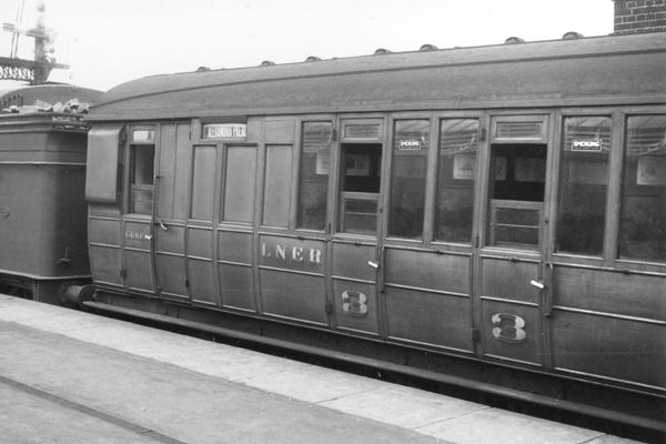
The brake end of 1924-built GNR/LNER Set No 71 at King's Cross in the late 1930s awaits departure for Alexandra Palace. It has the characteristic rebated guard's end and ducket, and two changes have already been made with addition of an illuminated destination board (from 1929); and elimination of the opening toplights in the passenger windows in favour of full glazing. By chance the same Set was also photographed in BR days, see below. Photo: HMRS ABJ023.
Click on the image for an enlargement
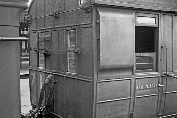
The outer end of GNR/LNER Set No 71 shows the external fittings quite well with the lighting switch in a mid-position, across the end windows. Note how well the teak appearance on the steel guard's ducket has been grained. Photo: HMRS ABJ024.
Click on the image for an enlargement
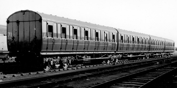
Seen from the inner end, former composite quadruplet E86260-3E from Set No 71 is interesting in several ways for this is one of the 1923-24 GNR/LNER sets with recessed guard's end and ducket, and the same Set as shown above. The toplights in the passenger windows had already have been removed; now the toplights on the doors have been removed and panelled. Photo: Author's collection.
Click on the image for an enlargement

This image is taken from an article I ran many years ago and despite the iffy quality, is useful for showing the outer end and the roof details.Photo: David Percival

The outer end of Set No 76 taken at Hatfield in 1965 showing the later arrangement of the fittings. Note how the train alarm gear was fitted off-centre. The lighting switchbox is now slightly larger and placed lower, along with a longer lever. This arrangement required the set number to be moved to the right. Some of the panelling has been repaired. Photo: Denis Seabrook, LNERS.
Click on the image for an enlargement
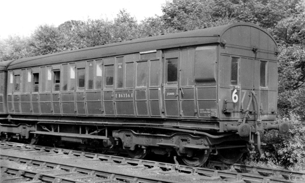
Now for something a little complicated.... During WWII, Set No 67 was hit by the Luftwaffe and three carriages were destroyed (and replaced, see below). This is the end that survived. Note the Gresley 8' heavy bogies fitted to these sets. The toplights had been modified as described although a single door had, unusually, gained a ventilator bonnet. Seen after withdrawal in 1967. Photo: Author's collection.
Click on the image for an enlargement

The outer end of Set No 67, similar to the end of Set No 76. Photo: Author's collection.
Click on the image for an enlargement

A detail view showing the Gresley 8' heavy bogies as fitted to the hybrid sets. Note how thin the partitions between the compartments were; quite a challenge for modellers. Toplights over the doors had been replaced by panelling. Photo: Author's collection.
Click on the image for an enlargement
LNER sets of 1925-28
In the final series the rebate in the guard's end was omitted along with the ducket, making for a more streamlined and more modern appearance.

In this post-War scene from 1946, N2 2674 is near Hadley Wood with an LNER-built "quad-art" train coming out of the sun. The set number, 93, can just be made out on the end carriage. Note the ventilator bonnets over the doors. With apologies for the mucky state of the picture - AG Ellis copied many pictures with, it has to be said, varying degrees of success. Photo: AG Ellis
Click on the image for an enlargement
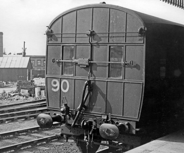
An undated view believed to be from the LNER period of the outer end of Set No 90. The lighting switch is in the mid-position and the train alarm gear is mounted vertically. Underneath the set number there is neither KING'S CROSS nor KING'S X which I suspect wasn't added until BR days. Photo: HMRS ABJ 520.
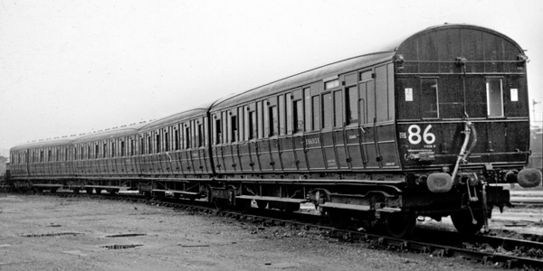
A BR-period view of the brake end of an LNER all-3rd quadruplet E86312-5E from Set No 86 after overhaul. The ventilator bonnets over the doors have been removed and the area panelled. The small text underneath the set number states "KING'S X". The lighting switch appears to have been moved to just above the buffers. Photo: Photomatic
Click on the image for an enlargement
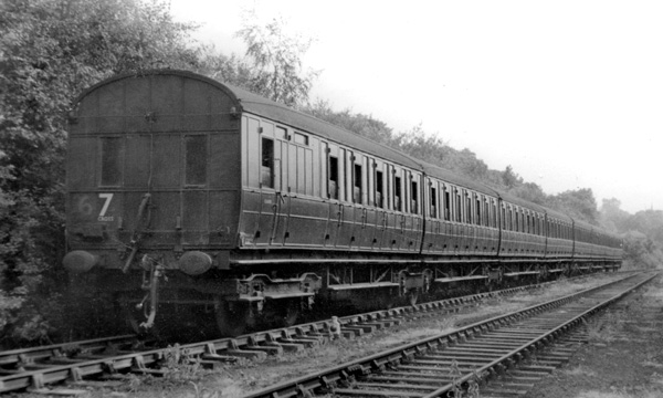
A general view of Set No.67 after withdrawal in 1967 at Dore & Totley, awaiting disposal. Nearest the camera is one of the replacement carriages from Set No.92. Photo: Author's collection.
Click on the image for an enlargement

The outer brake end which came from Set No.92. Photo: Author's collection.
Click on the image for an enlargement
A Kirk-based model
Being made from Kirk kits, much will be familiar to modellers and I only took a few pictures of the areas which differed from normal kits.
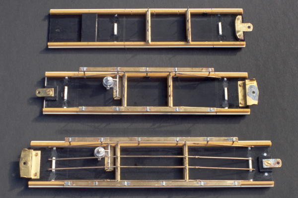
This composite view shows three stages of assembly of the underframes:
Top - A fresh floor made out of black Plastikard. White .020"x/020" PK was added along the edges of the steps to increase their width. The solebars are from the kit, upon which MJT needle beams and truss posts have been fitted, into slight notches. The raised black PK on the left is a locating point for the end bogie. On the right is a brass mount for an articulated bogie.
Middle - On the right is part of the MJT system of articulated compensation "CCU" riding on MJT bogies, each of which had a 12BA bolt fitted centrally to provide a simple physical connection (rather than the press studs supplied). The CCUs were attached to the floor pan with normal bolts through elongated holes so that the spacing between carriages could be adjusted according to the track curvature on your layout. CCUs were only fitted between the outer carriages: the other bogies rode freely in traditional 3-point compensation.
The suspended steps have been made up using brass (3x1mm "L" for the step and 1x0.3mm strip for the hangers) and were fitted into 1.2mm holes drilled in the solebars to give a truly secure fit. To ensure the same height throughout I made thick spacers against which the height could be set accurately for each step.
The trussing was also MJT, the 61'6" version cut to the required length and doubled up with a lap joint for strength.
Bottom - Now the purpose of the .060" square white Plastikard with gaps sawn through and laid at the outset becomes evident, as anchor points for the central trussing.
Click on the image for an enlargement
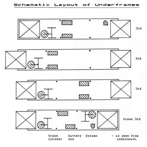
Many years ago I ran an article in the Modeller, a pretty basic one, and have copied this sketch showing the arrangement of the fittings on the underframe.
Click on the image for an enlargement
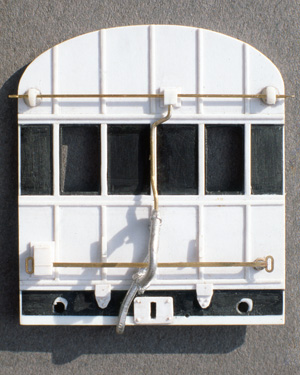
One of the outer ends, based on the Kirk moulding in black plastic, although it's hard to see the guard's end windows. I sanded the surface smooth, adjusted the outer dimensions, then built up the panelling and beading using Plastikard. There's a lot of lovely detail here which is a joy to see on the layout. The lever for the lighting switch is not available anywhere to my knowledge and I was fortunate to have them in my spares bin having come from some really old Kemilway etched kits. They could do with being added to a corner of manufacturer's etching and sold separately, albeit with limited sales potential: it's a classic small item which is ideally suited to the etching process. The hose is an ABS casting which has been formed to shape (in hot water helps).
Click on the image for an enlargement

The finished end numbered for Set 84 using PC Methfix transfers. The buffers came from MJT with the heads reprofiled to the required shape.
Click on the image for an enlargement
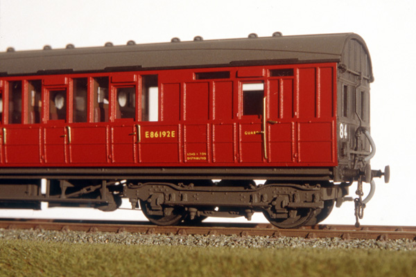
The side view of the outer end shows the delightful cluster of fittings. Since building this model I learned that the guard's vertical handrail and the lever handle to the door alongside were ferrous fixtures and should have been painted black. The interior shows well thanks to the thin supports between the windows.
Click on the image for an enlargement

All the articulated bogies were fitted with 12BA bolts like this, with the carriages resting on them, enabling the quadruplet to be assembled or disassembled easily on the layout. This is a compensated bogie with the CCU resting on it.
Click on the image for an enlargement

A side view of the outer end carriage whose underframe had a lot of fittings. Most of the others were quite spartan. Note how the ends of the seats are visible through the windows. The partitions and the seats had to be cut accurately to fit between the glazed sides.
Click on the image for an enlargement
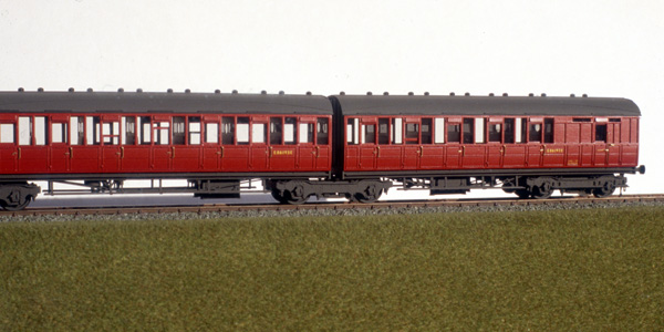
I was never able to photograph the complete set hence this general view of two outer carriages. Note how different the two underfames are.
Click on the image for an enlargement
LNER/ER King's Cross suburban services are here.


